New Stadium - Tottenham Hotspur Football Club
Raking Cable Support Scaffolds
The Brief
The Tottenham Hotspur Stadium roof was the first of its kind. Designed by Schlaich Bergermann Partner and constructed by Severfield, it was formed of two inner tension rings and a perimeter compression ring. The rings were connected in 54 radial locations using an upper and lower high tensile cable, in turn these cables were linked vertically using 5 ‘flying columns’.
The roof lift was extremely elaborate, involving 216 strand jacks which were simultaneously tensioned, making it one of the most complex lifts ever completed in the UK.
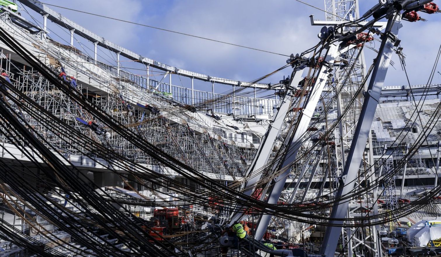
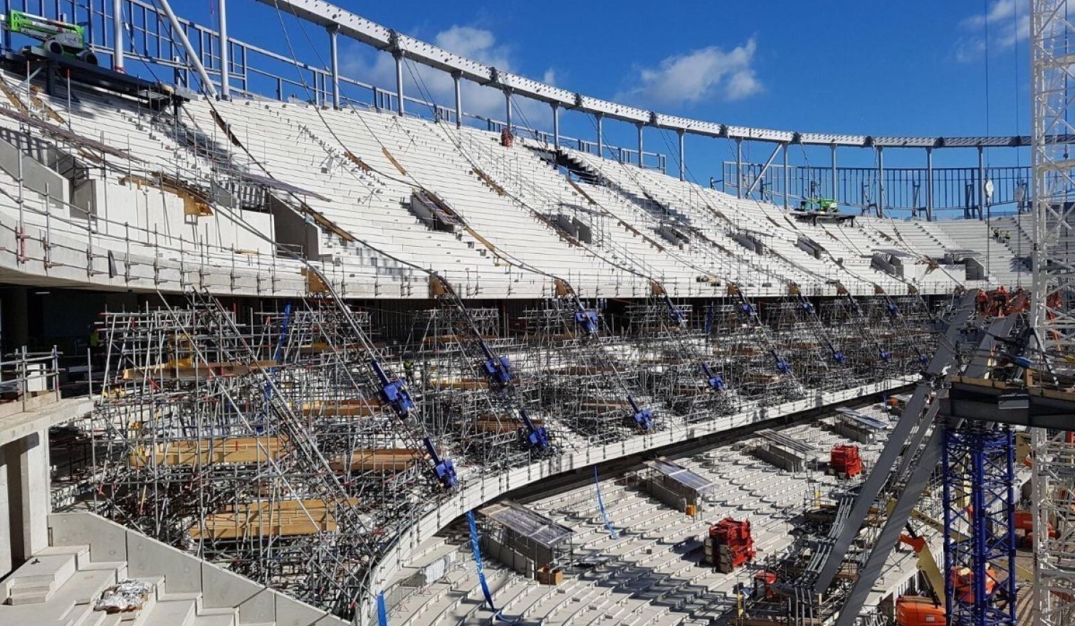
The cables which linked the outer compression ring at Level 9 to the inner tension rings at pitch side were extremely delicate and susceptible to damage.
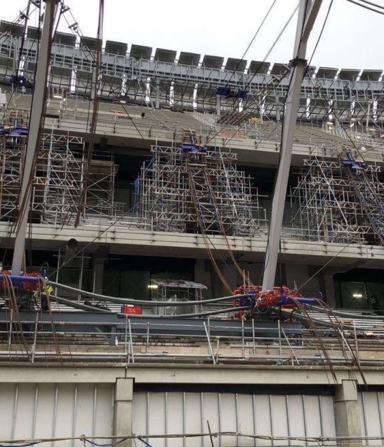
A bespoke ‘raking scaffold’ solution was developed which was capable of supporting both cables and the heavy strand jacks. This ensured a smooth transition from tier to tier. Had this not been done, the cables would have dipped sharply and become permanently kinked. Safe access was also required to all columns and strand jacks to allow connections to be made and inspected prior to the lift.
The Work
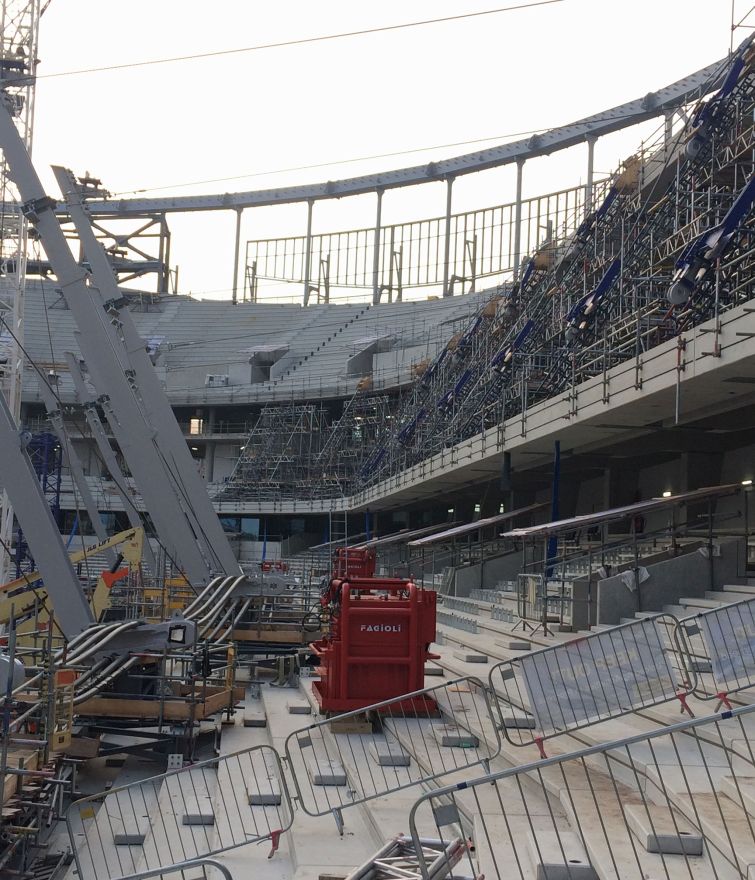
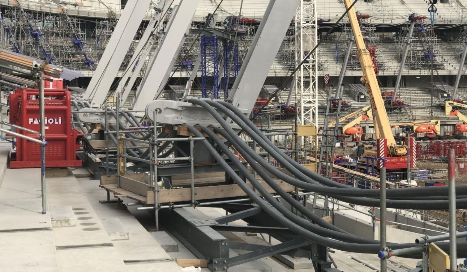
Each scaffold was to remain entirely freestanding and support two strand jacks which weighed in excess of two tonnes each. This coupled with the self-weight of the cable and scaffold itself resulted in high concentrated loads. As the scaffold was founded onto precast concrete terrace units with a span of greater than 10m, specific design considerations were made to ensure the units stayed within their allowable limits.
The design also made allowance for the interface created between the moving strand jacks and braced supporting beams throughout the tensioning process. This movement also meant that the location, direction and magnitude of load continually changed during the lift.
The Result
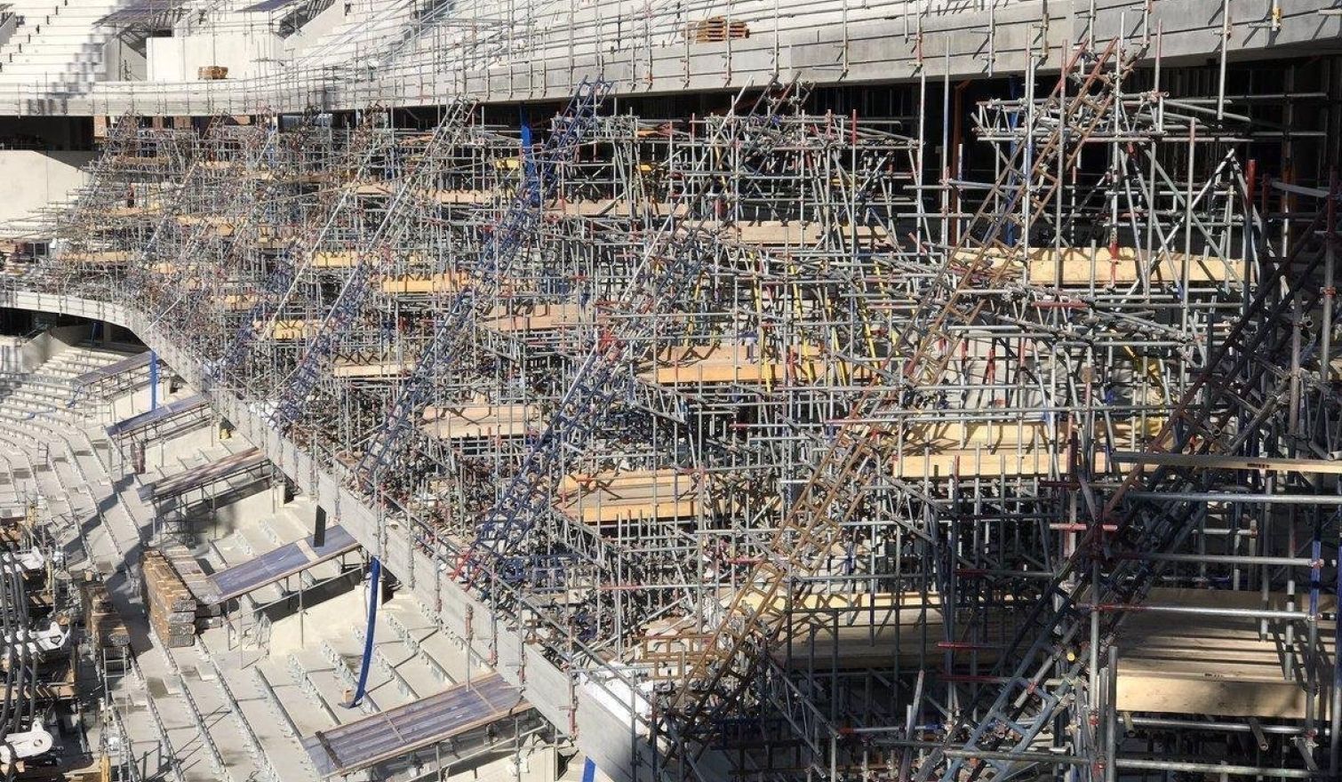
Beams were introduced in both directions to the base of the scaffold to share the load into multiple terrace units and then further distribute the load along the unit’s span. Footing details were designed to spread the load and protect the finished surface. Exclusion zones were identified to ensure additional load was not accidentally applied to the terrace throughout the duration of the works.
A lacing and bracing arrangement was developed to ensure no clash existed between the jack and the supporting beam arrangement, the movement was then simulated to identify worst case loads, directions and locations.